Installation Instructions -
Seip electric door operators
Procedure for fitting a Seip electric operator to a horizontally
tracked one-piece up & over garage door
(the procedure for
fitting to sectional type up & over doors is similar)
A 13mm spanner, 10mm & 13mm hex sockets & wrench, pair of side cutters or combination pliers, hammer, pencil, No.2 Pozi-screwdriver, electric drill, 5mm HSS drill, 5.5mm masonry drill, a 'pump action oilcan' filled with car engine oil, small step ladder.
| Before
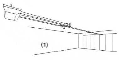
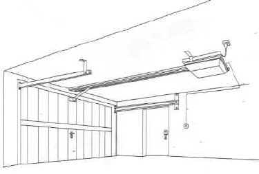
Getting Started 1/ A minimum clearance of 35mm is required between the top of the door and the ceiling/beams for the C-rail track. Note:- if you have insufficient clearance for the track, the operator can be mounted on the ceiling to the rear of the garage and connected to the door with an extended door arm as shown: (1) |
 |
 |
Contents
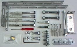
of the installation hardware pack One pair of motor support brackets, door header bracket & bolt, a selection of fixing screws, washers & masonry plugs, a small screwdriver, an Allen key & a bag containing eight track securing grub-screws & two emergency-release cable clamps Units supplied by Amourelle also include an additional pack containing 7mtrs of connecting wire & clips for the internal control switch, 1Mtr of red P.V.C. sleeving for the emergency manual release cable and a label for the door with instructions detailing how to operate the door in the event of a power failure |
The ideal position is 50 - 100mm above the door.
Seip operators include a Bowden cable operated emergency door-release device to allow manual operation in case of power failure, this can be operated either from inside the garage, or from outside by means of the original locking door handle if you have a 'vault type' garage (no personal access door)
Secure the end of the emergency release cable to a fixing on the back of the door garage, this will enable manual operation from inside the garage by pulling the cable.
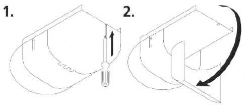
To enable the door to be released from outside with a key the emergency release cable should be connected to the original locking door handle as follows:
|
|
Connect
the emergency release cable to the back of the door's original
handle so that when the handle is unlocked
and turned from outside it pulls the cable downwards. The sketch
is only a guide as door handles vary according the make of door.
Note :- Do not leave the garage and close the door until you have tested the operation of the emergency release from outside. Get someone to test for correct operation of the handle & cable etc. while you are inside. |

| Mounting
the push button control switch Pry out the rocker plate from the front of the grey wall control switch to reveal the cover fixing screws, remove the cover and fix the switch housing to the wall near the exit of your garage at a minimum height of 1.5 mtrs. using the two No 8 x 30mm screws & wall plugs provided. Take a length two core bell-wire, separate & strip the insulation back 10mm and insert one wire into the upper clamp terminal and one wire into the lower clamp terminal on the push button switch module, then re-assemble the wall switch. |
 |
1/ Your Seip door operator will require a 13A mains power point positioned on the ceiling approx. 3.4mts back from the centre of the door frame. (alternatively a 13A extension lead can be run from an existing point)
For the final adjustment procedure refer to the manufacturers installation manual enclosed with the operator
Open and close the door making sure that the motor stops at least 30mm before the door reaches the door support track end buffers when open, and stops without applying excessive pressure against the frame when closed. (too much force will result in the manual release device being stiff to operate)
Stand outside and start the door in the CLOSE direction, when half closed, restrain the door by hand and check that the motor stops and reverses when hand pressure is applied to the lower edge of the door, a similar test should be carried out during the OPEN phase to make sure the door stops when hand pressure is applied to the lower edge of the door
The Installation is now complete ! - Relax & enjoy many years of effortless luxury & convenience !
The motor will automatically lock the door at the top when closed. If physical security is an important issue Amourelle's unique Securi-Dor multi-point locking system can be fitted to enhance your security by automatically engaging additional side latches on the door when closed.
This device can be fitted to your Seip garage door operator for added safety
Fitting instructions are supplied with the Infra-red break-beam safety detector kit
The above fitting instructions have been re-written by Amourelle Products with the help of years of first-hand experience to make the installation procedure as easy as possible.
If you require assistance ring 01384 900 264 - Help is just a phone call away !