|
Installation Instructions -
Seip operators to barn doors |
|
|
|
To be installed in conjunction with Amourelle Products model AP2006 barn door operating arm system Maximum Door
Opening Width |

A 13mm spanner, 10mm & 13mm hex sockets & wrench, pair of side cutters or combination pliers, hammer, pencil, No.2 Pozi-screwdriver, electric drill, 5mm HSS drill, 5.5mm masonry drill, can of oil, small step ladder.
Lubricate the door hinges and check that the doors move freely without rubbing or catching and make sure they close together snugly at the bottom.
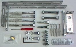 |
Contents
of the installation hardware pack One pair of motor support brackets, door header bracket & bolt, a selection of fixing screws, washers & masonry plugs, a small screwdriver, an Allen key & a bag containing eight track securing grub-screws & two emergency-release cable clamps Units supplied by Amourelle also include a length of red sleeving for the emergency manual release cable and a label for the door detailing how to use it |
Unpacking
and assembling the track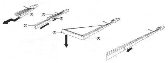
1/ Close the doors, measure the centre of the doorframe and mark this position on the frame header
Note :- check that the door-frame header is securely fixed at the centre, add additional fixings if necessary.
Note :- If you have a high ceiling it may be necessary to extend the fixing brackets
a) Lay the AP2006 door arms on the floor, swap the arms if necessary to suit door handing by reversing the 'L' arm (the hockey stick shaped bracket) thus enabling the shortest arm to be attached to the door that is rebated to close first. (as delivered, AP2006 arms are assembled for the LH leaf to close first when viewed from outside)
Important: The bolt attaching the hockey stick bracket to the main arm should be fitted with a nyloc nut & wavey washer and tightened so as to allow the bolt to rotate and thus function as a pivot point to allow the two arms to swing apart freely. Check that the M8 locking nut on the swivel bracket at the end of the arms is secure but not too tight because it is essential that the swivel bracket can rotate freely by hand
 Arms configured for RH leaf to close first (when viewed from inside) |
 |
 Arms configured for LH leaf to close first (when viewed from inside) |
b) Make a pencil mark at the top of both doors 1 mtr
from the hinged edge, 50mm down from the frame header
(with AP2006/HDkit fix arms to doors at 1.2mtrs - AP2006/W
fix arms to doors at 1.6mtrs)
c) Attach the arms to the sliding trolley of the operator using
the M8 nyloc nut & bolt then fix the
other ends of arms to the doors at the 1 mtr. pencil marks the using 8mm
x 40mm coachscrews supplied.
Hint: use a strap to support one arm while attaching the other arm to
the door
d) Lubricate
all moving & sliding parts with oil. (engine oil recommended)
Note: To prevent loss & damage from forced entry
the Securi-Dor AP2007 bottom
locking
device can be fitted to
automatically secure the doors at the bottom when closed.
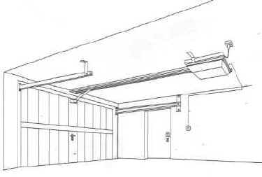
Seip operators include a cable operated emergency door-release device to allow manual operation in case of power failure, this can be operated either from inside the garage, or from outside by means of a locking door handle if you have a 'vault type' garage (with no personal access door)
Run the emergency release inner cable horizontally along the R.H. door operating arm (viewed from inside) and secure the end of the cable to the spare fixing hole on the arm, a length of red P.V.C. sleeving is supplied for the cable. This will enable manual operation from inside the garage by pulling on this red cord.
opening the garage doors from outside in the event of power failure.
Amourelle supply a suitable locking handle and bowden cable kit for this purpose, the external release lock kit should be connected to the Seip operator's manual release mechanism as follows :-
Fit the locking handle to the face of the door that closes last using the fixing hardware supplied, fit the outer cable stop-end bushes to the door and door arm (as described in the instructions enclosed with the external release kit.) Run the inner cable from the manual release lever on the sliding trolley horizontally along the door operating arm, down through the length of outer brake cable to the door and connect it to the back of a locking handle so that when the handle is unlocked and turned from outside, it pulls the cable downwards.
Note: Do not leave the garage and close the doors until you have tested the operation of the emergency release from outside. (get someone to test the handle for correct operation while you are inside)
|
|
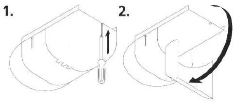
Run the bell-wire back to the motor head securing it with cable clips along the route, open the motor casing as shown in Figs 1 & 2, pass the bell-wire through a grommet at the rear of the motor chassis and connect the wires to terminals A & B on the Seip TS75 P.C.B.
Your Seip door operator will require a 13A mains power point positioned on the ceiling approx. 3.4mts back from the centre of the door frame. (alternatively a 13A extension lead can be run from an existing point)
For the final adjustment procedure refer to the Seip TS75 installation manual enclosed with your operator.
Amourelle will despatch your Seip TS75 / AP2006 barn door operator kit pre-configured ready for installation to barn doors with the TS75's logic control module adjusted so that the motor's safety stop system functions correctly when fitted to side hinged doors
Open and close the doors and make final adjustments to the red actuator trips, the close limit actuator should be adjusted to provide 5mm of free 'play' in the sliding sections of the door arms when the doors are closed.
Provides a means of opening the garage door from outside in the event of power failure
if you have no alternative access door.
Securi-Dor bottom locking will provide unrivalled security by automatically
locking the doors at the bottom when closed.
(a label with operating instructions for the manual release cord is also supplied)
The Installation is now complete ! - Relax & enjoy many years of effortless luxury & convenience !
These fitting instructions have been written by Amourelle Products with the help of years of first-hand experience to make the installation procedure as easy as possible.
If you
require assistance ring
01384 900 264
- Help is just a phone call away !
|
|
|