Securi-Dor
AP2000 AUTOMATIC SECURITY LOCKING SYSTEM
(Protected by UK patent application No. 9619157.2)
For the automation of the original manual latches on one-piece retractable remote controlled garage doors
FITTING INSTRUCTIONS
For use on one-piece retractable garage doors with either
cable operated or sliding rod type latch systems
compatible with most electric operators (not
compatible with Swift Challenger & Henderson/Sommer operators)
1. Close the door and
check that the top wheels are not supporting the weight of the door when closed as this
can prevent the door from closing properly at the bottom, adjust the track position on the
doorframe if necessary, check the door alignment and check that the existing manual side
latches or sliding bars engage freely onto the striker plates.
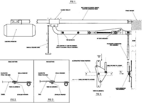
2. Remove the straight connecting bar
linking the operator sliding trolley to the door bracket. (and 'L' bracket if
fitted)
3. Pull the manual disconnect cord to
disengage the operator and fit the new connecting bar assembly in place of the original,
an 'L:' connecting bracket may be used as in Fig 1 to improve horizontal
alignment if required. (it may be necessary to reposition or modify the door header
bracket to give clearance for the de-latching lever on the new assembly)
4. Remove the original lock cam mechanism from the back of the door handle,
retain the latch cables or rods for re-use.
5. Fit the 1/2"dia
telescopic connecting rod over the 3./8" rod and fit the new latch operating
cam assembly at a central position on the door at a height corresponding to
the existing side latches using the two 4.8mm pop rivets supplied.
Note: If the door has
rigid bar type locking continue to stage 7 and then use stage 6 to make final adjustments
to the latches.
6. Adjust the telescopic connecting rod
length to achieve a cam plate angle as shown in Fig 4, then secure the telescopic joint
with the two self-drilling, self tapping screws supplied.
7. Connect the two original rigid latch
bars (as fig 3) or side latch cables (as fig 2) to the rear of the latch operating cam
assembly using Ľ" clevis pins, penny washers & starlock washers, (supplied)
ensuring that the RH rod or cable is connected to the upper pivot pin. Adjust cable lengths so that the door latches are withdrawn by 5mm.
8. Lubricate all moving parts on the Securi-Dor device, door arm
pivot points & rollers etc. (engine oil recommended)
9. Re-engage and carefully run the
electric operator and re-set the open & close limit stop adjustments making sure that
the new connecting bar assembly is compressed to 80 - 90% of its travel when the door is
closed. Note :- It is recommended that a door stop is fitted
to the top of the door to limit unwanted door movement and stress when the door is fully
closed.
10. Check the operation of the latches
and make final adjustments making sure the latches engage when the door is closed by the
electric operator, and release prior to opening, also check the safety-stop system and
make adjustments to the trip sensitivity if necessary.
• Home Page • Site Index • Installation Service •